lingo.lol is one of the many independent Mastodon servers you can use to participate in the fediverse.
A place for linguists, philologists, and other lovers of languages.

Server stats:

64
active users

#opengl

2 posts2 participants0 posts today

Yay! Last-minute success! (only for left-to-right rendering, though)

It appears like I have the scaling working correctly and SDF fonts are rendering as expected. It's even working pretty nicely with the text sizing demo! It looks like I still have a bug with the text bounding box but, visually things are looking much better.

Hey #OpenGL and #graphics people, are there any graphics profiling/instrumentation/frame debugger solutions which work with OpenGL on modern non-Windows systems? Something à la #RenderDoc but that works on #Wayland or Apple Silicon Macs. To do frame debugging right now I have to log out of my Wayland session on my #Linux desktop and log in to #X11, which is uber-broken on my mixed DPI fractional scaling multi monitor setup... #programming #graphicsprogramming #macdev

Replied in thread

@grumpygamer generally like having multiple options to be able to check and help with graphics drivers bugs on Linux. Was also surprised that #OpenGL was seemingly faster than #Vulkan with @play0ad on my Lenovo T14s AMD gen3 laptop (only checked briefly though). I'd mostly be concerned about cross platform compatibility, but I guess Vulkan has you covered there. And it's also a little less of a concern for me since #Wine / #Proton and #DXVK have made such a tremendous progress in the last years.

Went to go remove any #microsoft games from my #Steam wishlist, only to realize I don't have a single one on there. No #activison, no #bethesda, no #blizzard. Turns out I haven't really been microsoft's main target for a while. I don't use #Windows. Never used #Bing. Don't write programs with #DirectX, I use Vulkan and #OpenGL and #SDL. Don't use #OneDrive. Never used #Skype. Don't use an #Xbox #controller on my PC, I use an 8bitdo controller. Don't use #Azure. I am disconnected from them.

Testing the Gosper curve in my variable iteration halftoning setup. So far I've only used the Hilbert curve this way, and things get a bit coarser with the Gosper, so it was harder to find images that make nice results. So here we are with the old Venus again.

The number of points multiplies by 4 for Hilbert and 7 for Gosper on each step, so the latter has to get by with fewer iterations for a sensible resolution. Here we have 6 iterations for 6 grey levels.

In the last post, Tis Veugen suggested dithering with the Gosper curve. At first I thought this doesn't make sense, since the curve lives on a hexagonal lattice, while dithering is generally done at the native pixel level, which means a square lattice. But as I thought about this further, it started to look like a fun challenge. Besides, the square grid hasn't always been the native way to organize pixels; for example, some old CRTs also used a hex lattice.

So I was really just making up excuses for the extra work. First I had to set up interpolated sampling, which would come for free in OpenGL, but now I was working on the CPU. The Gosper curve was also new to me, and I implemented it in my own way from first principles using IFS ideas, like I'd done earlier with the Peano curve.

For comparison, here's also a version with the boustrophedon curve on a hexagon, since I already had that curve function in my toolbox. Finally there's also the raw Gosper curve, though a smaller version to give a clearer idea.

The previous demo made me dig deeper into dithering algorithms. It's something I should have done years ago, as I've been using simple random dithering now and then, and I hadn't even thought of gamma correction. One algorithm in particular caught my eye: Riemersma dithering, which uses the Hilbert curve. Compared to the usual matrices for error diffusion, the curve approach seemed easier to implement in some ways, as it has fewer edge issues.

More interestingly, it struck a chord with my earlier experiments with space-filling curves in image processing. So it was a kind of familiar territory, but it also seemed esoteric enough that I could imagine making some new discoveries. For example, play with other plane-filling curves besides the Hilbert.

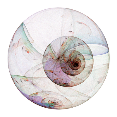
The first image uses the boustrophedon curve, which makes the vertical wave patterns I recall from a number of non-dithering demos. The second curve is what I call the diagstrophedon, a diagonal zig-zag starting from the top left corner, and I think its wavy artefacts make a nice match for Venus's hair.

Then in image 3 we have Hilbert, which doesn't seem to make any particular artefacts, and I guess that's a good thing for dithering. Finally 4 uses the Peano curve, which makes some fun wiggles in light areas.

Yet another optimized Voronoi tiling. This was supposed to be a simpler alternative to the previous tiling approach, but I ended up going down a rabbit hole of various dithering algorithms.

Instead of the equal-sum partitions, this uses regular dithering to find the Voronoi seed points, and the tile areas are inversely proportional to the colour values. My simple random dithering didn't work as well as expected, so I started to look into alternatives. I was of course aware of Floyd-Steinberg, and as I grew a bit tired of this demo, I ended up cheating a little by using a ready-made library. Since I was using PIL for image handling anyway, I could simply use its format conversion functions to get a 1-bit image, which uses F-S by default.

As before, I planned to use edge detection to get smaller tiles at the contrast edges. However, it didn't work so well with dithering, as it would concentrate basically all seed points at the edges. So here I used a mix of edge detection and the original. I think it worked out nicely here, as the bright colours often coincide with areas of small detail, while the dark background doesn't need much resolution.

I wanted to make the optimized tiling look more organic, and I've already played with Voronoi diagrams quite a lot. But this turned out a bit more messy than expected. To preserve the size and shape variations of the rectangles in the Voronoi cells, I ended up using a non-uniformly weighted metric. I guess it counts as a shape metric, using the definition in my Bridges 2020 paper.

As before, there's a roughly uniform tiling with an equal number of cells for comparison.

Another visual refinement to a recent demo: adding seams to the optimized tiling scheme. While it breaks the mosaic illusion to some extent, I think it makes the tile sizing idea much clearer. As before, there's a uniform variant with the same number of tiles for comparison.

Source photo: Mary of Egypt by José de Ribera, in public domain.

How it was supposed to look like in the first place: rounded with Bezier curves.

I've used Bezier curves and Hermite splines quite a lot to smooth out progressions of discrete points, such as Hamiltonian circuits. The challenge with this Hilbert curve is that there are tens of thousands of points, so drawing a nice OpenGL shape for each edge gets rather slow. Of course, this isn't a deal breaker for still images, but I like making my code efficient.

I've now constructed the Bezier curves in geometry shaders. I've used those for some time to draw simpler shapes more efficiently, such as line segments with rounded ends; the idea is to do more work on the GPU, while moving as little data as possible there. These line segments only need the endpoint coordinates, as well as thickness and colour. The curves seemed more challenging due to the number of parameters, but in the end there weren't really any issues.

The recent stipplings and partitionings reminded me of this demo from about 2 years ago. In short, it's a Hilbert curve where the iteration level varies by the colour value. I wanted to make some small changes, but I ended up rewriting it completely. The shader approach seemed needlessly heavy and redundant for something that works more naturally on a CPU. But mostly it was just a fun exercise in looking at the same problem from a different angle.

The first picture shows the original idea. With the new idea, I wanted to get rid of the slanted lines; the result doesn't feel any better to me, but I guess it's interesting in its own way.

Last post's stippling was based on partitioning the image into rectangular tiles, with one dot per tile. I wondered what the tiles themselves would look like; they are basically pixels of different sizes, so they might give an interesting view of the original image.

At first, this didn't look too exciting. The stippling idea was to make brighter pixels smaller, but with the tiles fully coloured, the halftoning idea won't work, and the small pixels are lost in large bright areas.

I still thought the general idea could be useful in some other way. What if the image was partitioned according to contrast edges? Then we'd have smaller pixels where we need more detail. This seemed to work after some adjustments, including smoothing for noise removal.

The effect doesn't look like much on its own, but a comparison against uniform pixelation makes it clear: both pictures have 4096 tiles, but one has a nicer distribution of sizes matching the details.

Last post's line raster idea was kind of frustrating to get right, and I'm still not quite happy with the results. Of course, as soon as I'd posted them, I had a new idea for stippling images using the same 1D partitioning logic.

Now the binary partitioning proceeds alternately in x and y dimensions, splitting the whole image into areas of equal colour sum. It doesn't help with the line raster idea, and I'm not sure if it's great for general stippling either; it feels quite blocky compared to random dithering. But the technical idea seems quite fun — it should work in higher dimensions too.

I also made the minimum spanning tree, and it turned out quite interesting with the horizontal and vertical lines dominating large areas.

I came across this halftoning idea sometime last week. While the idea was relatively easy to understand and fun to implement, I've spent quite a lot of time trying to make the result look nice.

In each row, the image is split into bins containing roughly the same sum of lightness value. This is nice to implement when the number of lines/bins is a power of 2, so we can recurse with a binary split. Thus the line density varies by average lightness. The problem is that density is considered along the x-axis. If things change a lot between rows, the lines get slanted, so they appear more dense. Here I've included some averaging between neighbouring rows to make thing a bit smoother.

I'm also including a fun glitch from the early tests. The line-density system includes the set of point coordinates and the graph structure (which point is connected to which). What happened here is my generic graph generator that simply finds the nearest neighbours of each point. So in the light areas that are compressed horizontally, the nearest neighbours were left and right.

I've always found circuit boards aesthetically inspiring, and in recent years this fascination has turned into a number of PCB-styled demos. I think a key inspiration for these has been the "Absolut Intelligence" vodka advert a couple of decades ago.

I haven't done these in a while, but a week or two ago I ran into spanning trees. I noticed that spanning trees of square lattices can make rather nice impersonations of printed circuits, especially when the solder points are only put on leaf points. Cut the tree up into a forest, and it's making even more electrical sense.

Halftoning isn't new to me either, but my existing line-based techniques didn't look nice on the square PCB lattice. It had to be more blocky with exactly horizontal or vertical lines. So for this iteration, I've set each half-edge to have a constant width — a natural evolution of my earlier variants, which were built from half-edge sections. Of course, the solder points follow a similar areal scaling.

Continued thread

What I'd like to do is render these pieces in the correct orientation, including the grass bits on top, but somehow make the actual grass texture always appear such that it faces right-side-up, like it does on the unrotated flat ground.

How would I do this?